Wireless Lighting Control for Pre-Sales Engineers Day 4
 Moaath Al-Bukaai19 Oct 2026 · 29 min read
Where Does the Intelligence Live? Wireless Lighting Control for Pre-Sales Engineers
Day 4 of the Essentia pre-sales training series. Written for system integrators and engineers who specify drivers, controllers and wireless lighting control.
Day 4 of the training asked one question: where does the intelligence live? In a relay at the wall, or inside the light itself? Everything else that day, the drivers, CC versus CV, the transformer plus controller pattern, the downlights, strips and tracks, follows from that one choice.
Today's roadmap
Two architectures: control the circuit, or control the light.
What each one can, and cannot, do.
One light, three drivers, and who supplies the driver.
CC vs CV, transformer plus controller, and how to select.
Worked examples: downlight, striplight, tracklight.
Mistakes (do and don't), tips, and scenario practice.
The core idea: two ways to make a light "wireless"
The receiver can live at the wall, where it controls the circuit. Or it can live inside the light, where it controls the fixture.
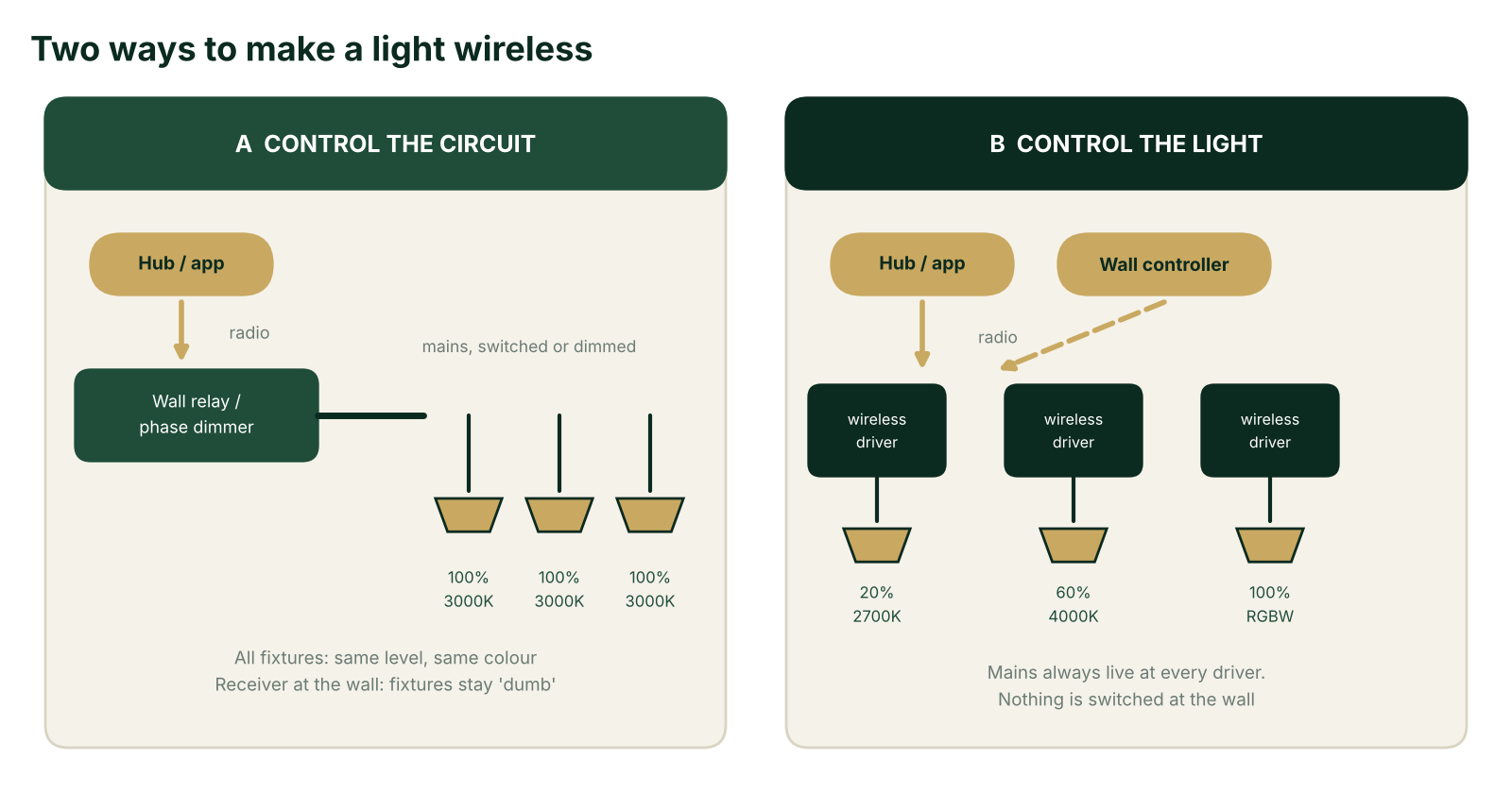
A. Control the circuit. A hub or app talks by radio to a wall relay or phase dimmer. The mains is switched or dimmed. All fixtures get the same level and the same colour. The receiver is at the wall, so the fixtures stay "dumb".
B. Control the light. A hub, app or wall controller talks by radio to a wireless driver in each fixture. Each light can sit at its own level and colour, for example 20% at 2700K, 60% at 4000K and 100% RGBW. Mains is always live at every driver, and nothing is switched at the wall.
Same fittings and same ceiling, but a very different capability. The radio (Zigbee, BLE mesh, Thread/Matter, Wi-Fi) can change. The question "where does the receiver live?" does not. In the diagrams, the levels shown in B are illustrative.
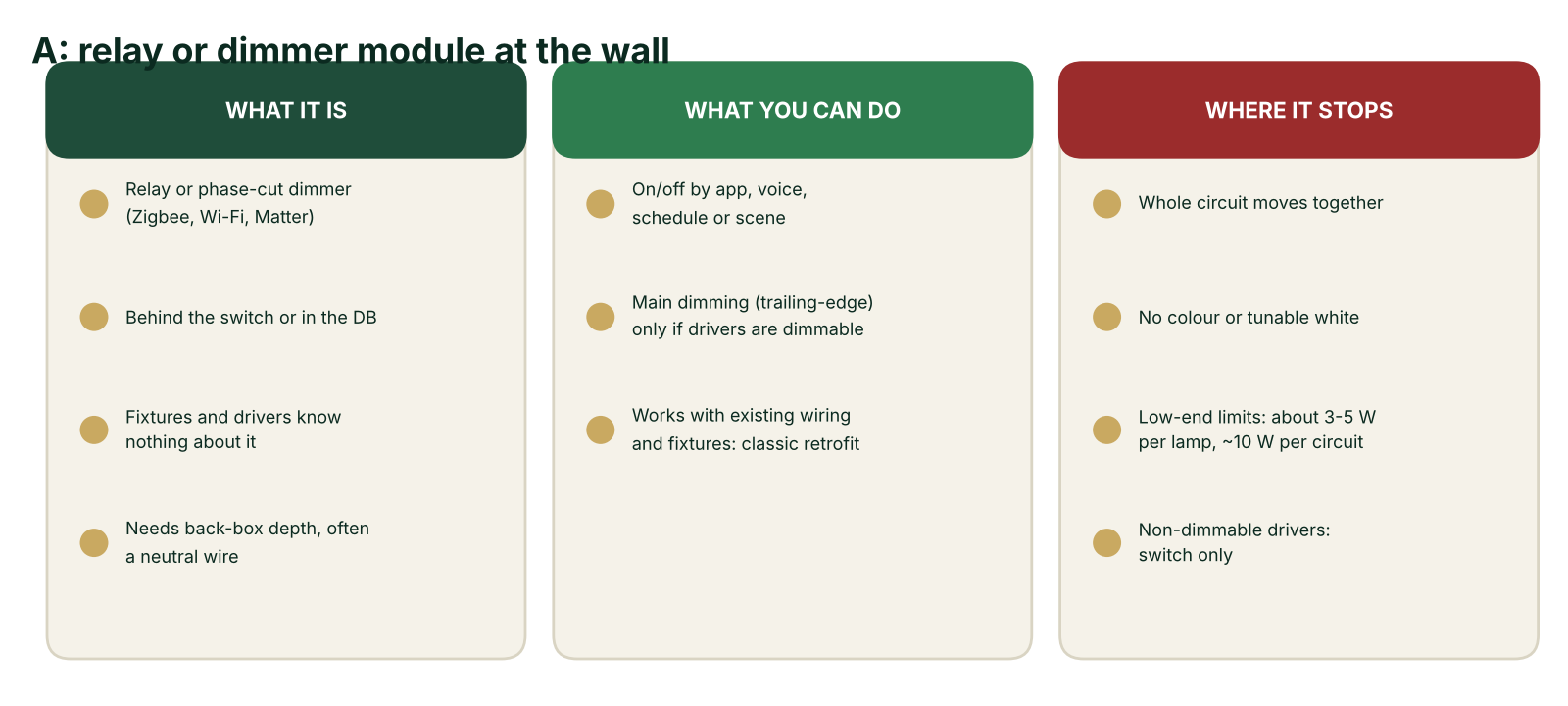
A: relay or dimmer module at the wall
Smart on/off, and at best main dimming, for everything wired on that circuit.
What it is
A relay or phase-cut dimmer module (Zigbee, Wi-Fi, Matter and so on) fitted behind the wall switch or in the DB.
It switches or chops the mains supply to the whole circuit. The fixtures and their drivers know nothing about it.
The module sits in the switch position, so it needs back-box depth, and often a neutral wire (some models work without one).
What you can do
On/off from app, voice, schedule or scene, per circuit.
Main dimming of the circuit (trailing-edge phase-cut), but only if every driver on it is phase-dimmable.
It works with existing wiring and existing fixtures, the classic retrofit route when nobody can open the ceiling.
Where it stops
Everything on the circuit moves together. There are no individual fixtures and no separate groups without separate circuits.
No colour or tunable white, because the module only sees mains voltage.
Low-end dimming is limited: typical modules need about 3 to 5 W per lamp and about 10 W per circuit minimum, and some drivers flicker. Test first.
Non-dimmable drivers can only be switched, never dimmed.
Rule of thumb: if the drivers on the circuit aren't phase-dimmable, the module can only switch on and off.
The minimum-load figures are typical of Zigbee phase-cut modules on the market (my notes cite Candeo C201/C204 at 5 W per lamp and 10 W per circuit, and C203 at 3 W). They vary by model. I did not re-verify them, so always check the datasheet and test with the actual driver before quoting.
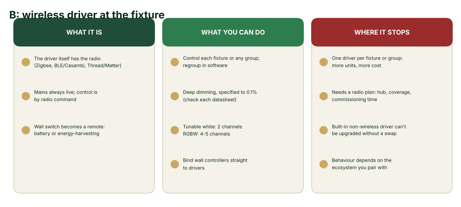
B: wireless driver at the fixture
The receiver is part of the driver, so every light becomes its own addressable device.
What it is
The LED driver itself has the radio (Zigbee, BLE/Casambi, Thread/Matter), or a wireless controller sits next to a standard driver.
Mains is always live at the driver. All switching and dimming is done by radio command, not by interrupting power.
The wall switch no longer needs a relay. It becomes a controller that only sends commands, battery or energy-harvesting (for example Zigbee Green Power), with no mains in the switch position.
What you can do
Control each fixture or any group, and regroup later in software, not with wiring.
Deep dimming: Sunricher Zigbee CC/CV drivers are specified down to 0.1% (one 2-channel model to 0.01%). Always check the datasheet.
Tunable white with a 2-channel driver, and RGBW with a 4 to 5 channel driver.
Pair wall controllers straight to drivers. A Sunricher Zigbee driver can bind up to 20 Green Power switches.
Where it stops
One wireless driver per fixture or group means more units and more cost than one relay per circuit.
It needs a radio plan: hub or coordinator, mesh coverage, pairing and commissioning time.
A fitting with a built-in non-wireless driver can't be upgraded without swapping the driver.
Behaviour depends on the ecosystem (hub, app, voice) you pair it with.
Key shift: the wall switch doesn't carry the load any more. It is just a remote. The capability now comes from the driver in the light.
I checked the Sunricher numbers against a retailer's datasheet for a 36 W two-channel tunable-white Zigbee driver (Simpex datasheet). It confirms 350 to 1050 mA set by NFC, up to 20 Green Power switches and Touchlink commissioning. It states dimming of 0.01% to 100% at maximum current, while my slide said 0.1% for that driver family, so quote the exact model's datasheet, never the family.
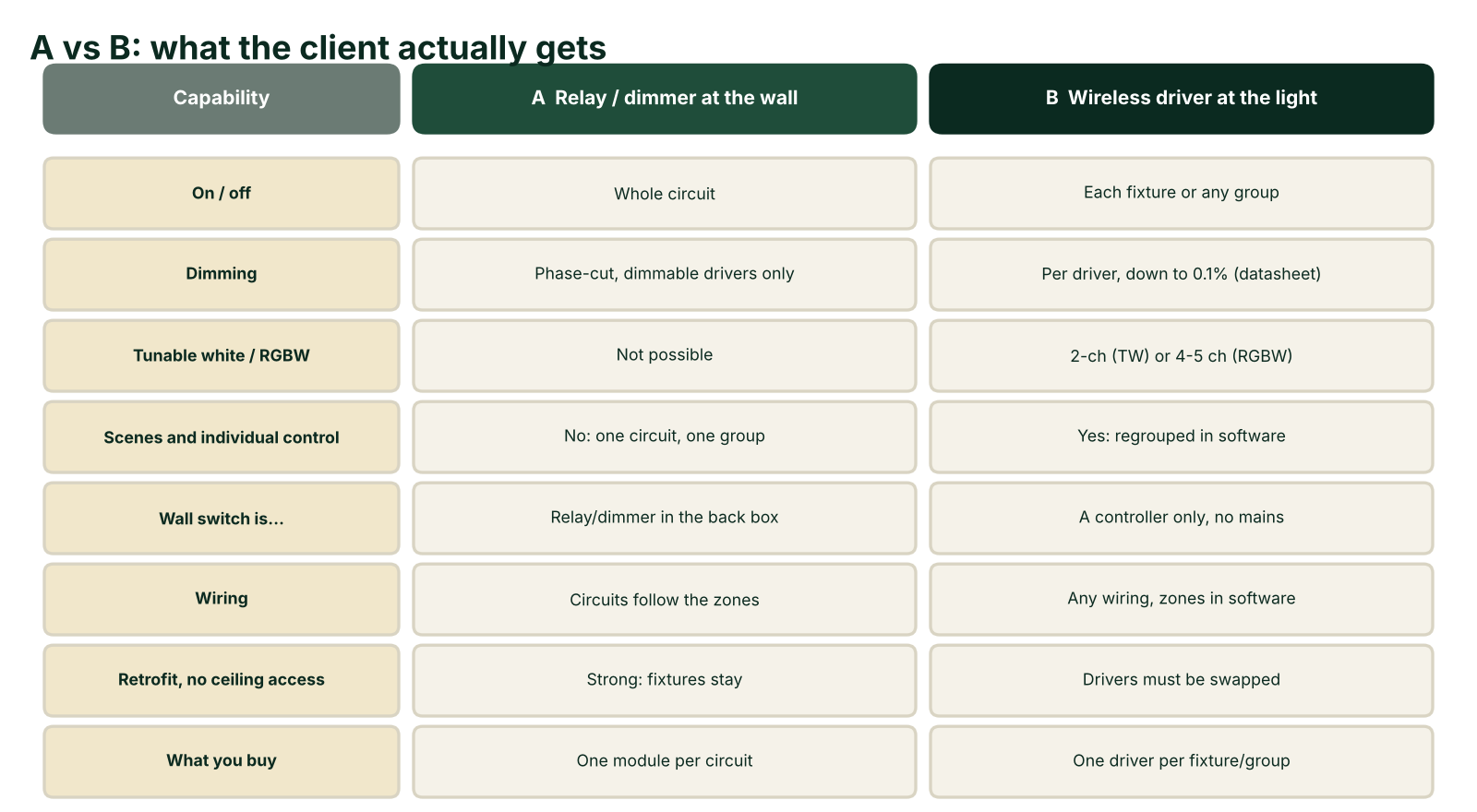
A vs B: capability at a glance
What the client actually gets from each architecture.
Capability | A: Relay / dimmer at the wall | B: Wireless driver at the light |
|---|---|---|
On / off | Whole circuit | Each fixture or any group |
Dimming | Main dimming via phase-cut, only on dimmable drivers; limited at low end | Per driver; datasheet-specified down to 0.1% on drivers like Sunricher Zigbee |
Tunable white / RGBW | Not possible | Yes, with a 2-channel (TW) or 4 to 5 channel (RGBW) driver |
Individual control and scenes | No: one circuit is one group | Yes: per fixture, regrouped in software |
What the wall switch is | A relay or dimmer in the back box (mains, depth, often neutral) | A controller only: battery or energy-harvesting, no mains |
Wiring | Circuits must follow the zones you want | Any wiring: zones are defined in software |
Retrofit, no ceiling access | Strong: existing fixtures stay | Needs drivers swapped or fixtures supplied wireless |
What you buy | One module per circuit | One driver per fixture or group |
When each approach is right
Neither is "better". They solve different problems, and real projects often use both.
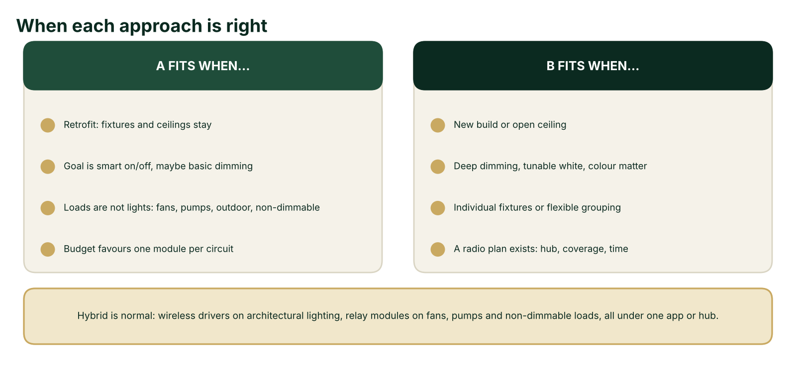
A fits when:
Retrofit: fixtures and ceilings must stay untouched.
The goal is smart on/off (maybe basic dimming) per room or circuit.
Loads are not lights: fans, pumps, outdoor feeds, non-dimmable fittings.
Budget favours one module per circuit over one driver per fixture.
B fits when:
It is a new build or the ceiling is open, so drivers can be specified from day one.
Architectural quality matters: deep dimming, tunable white, colour.
Individual fixtures or flexible grouping are required (and may change later).
A radio plan exists: hub or coordinator, coverage, commissioning time.
Hybrid is normal: wireless drivers on the architectural lighting, relay modules on fans, pumps and non-dimmable loads, all under one app or hub.
One light, three possible drivers
The same fitting can be built or quoted with a standard, a DALI, or a wireless driver.
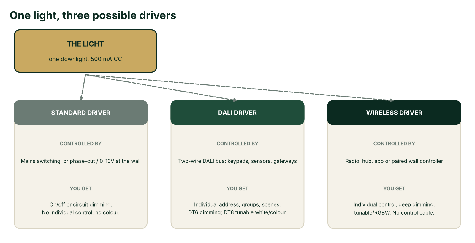
The light. One downlight, one LED module. It needs, say, 500 mA constant current. It does not care how it is controlled.
Standard driver. Controlled by mains switching, or phase-cut or 0-10V dimming at the wall. You get on/off or whole-circuit dimming. No individual control, no colour.
DALI driver. Controlled by the two-wire DALI bus: keypads, sensors, gateways. You get an individual address, groups and scenes. DT6 for dimming, DT8 for tunable white or colour (see Day 3).
Wireless driver. Controlled by radio: hub, app, or a paired wall controller (Zigbee, BLE, Thread/Matter). You get individual control, deep dimming, and tunable or RGBW with the right channel count. No control cable.
The light doesn't change. The driver decides what control is possible, and the driver is a separate product from the light.
Who supplies the driver?
Either the supplier quotes light and driver together, or we quote the driver on its own.
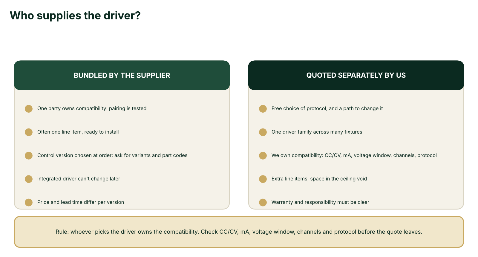
Bundled by the supplier:
One party owns compatibility: the pairing is tested.
Often one line item, ready to install.
But the control version is usually chosen at order. Ask which variants exist (standard, DALI, wireless) and their part codes.
An integrated driver can't be changed later without replacing the driver.
Price and lead time can differ per control version.
Quoted separately by us:
Free choice of protocol per project, and a path to change it later.
One driver family can be standardised across many fixtures.
But we own compatibility: CC or CV, current setting, voltage window, channels, protocol.
Extra line items, and space for a remote driver in the ceiling void.
Warranty and responsibility need to be clear in the quote.
Rule: whoever picks the driver owns the compatibility. If it's us, we check CC/CV, mA, voltage window, channels and protocol before the quote leaves the building.
CC vs CV: the spec you can't "make work"
The light tells you which one it needs. The driver has to match, not the other way round.
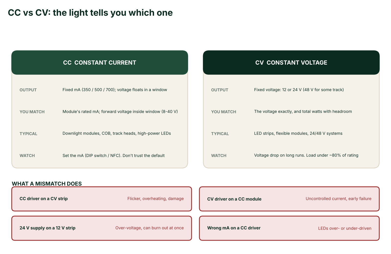
CC: constant current
Output: a fixed current in mA (for example 350, 500 or 700 mA). The voltage floats inside a window.
You match: the module's rated mA, and the module's forward voltage must sit inside the driver's voltage window (for example 8 to 40 V).
Typical lights: downlight modules, COB, track heads, high-power LEDs.
Watch for: many CC drivers are mA-selectable (DIP switch or NFC). Set it. Don't trust the default.
CV: constant voltage
Output: a fixed voltage, typically 12 V or 24 V (48 V for some track). Current depends on the load.
You match: the voltage exactly (a 24 V strip needs a 24 V driver) and the total watts, with headroom.
Typical lights: LED strips, flexible modules, 24 V and 48 V systems with current limiting built in.
Watch for: voltage drop on long runs, where the far end gets dimmer. Keep load under about 80% of the rating (rule of thumb).
What a mismatch does
Mismatch | Result |
|---|---|
CC driver on a CV strip | Flicker, overheating, damage |
CV driver on a CC module | Uncontrolled current, overheating, early failure |
24 V supply on a 12 V strip | Over-voltage, can burn out at once |
Wrong mA on a CC driver | LEDs over- or under-driven |
Inspired LED's driver guide agrees on the first row: a CC driver on a strip "will produce incorrect output and can damage the strip". It also gives the 80% rule: size the driver so the load does not exceed 80% of its rated wattage. My slide called that a rule of thumb, not a standard, and that is exactly how it should be treated. For the CC side, the Sunricher datasheet above shows a 350 to 1050 mA selectable window and a 6 to 54 V output range on one model, so the window really is wide and really does need checking.
Separate the power from the control
A transformer only provides the voltage. A low-voltage controller between it and the LED adds the technology.
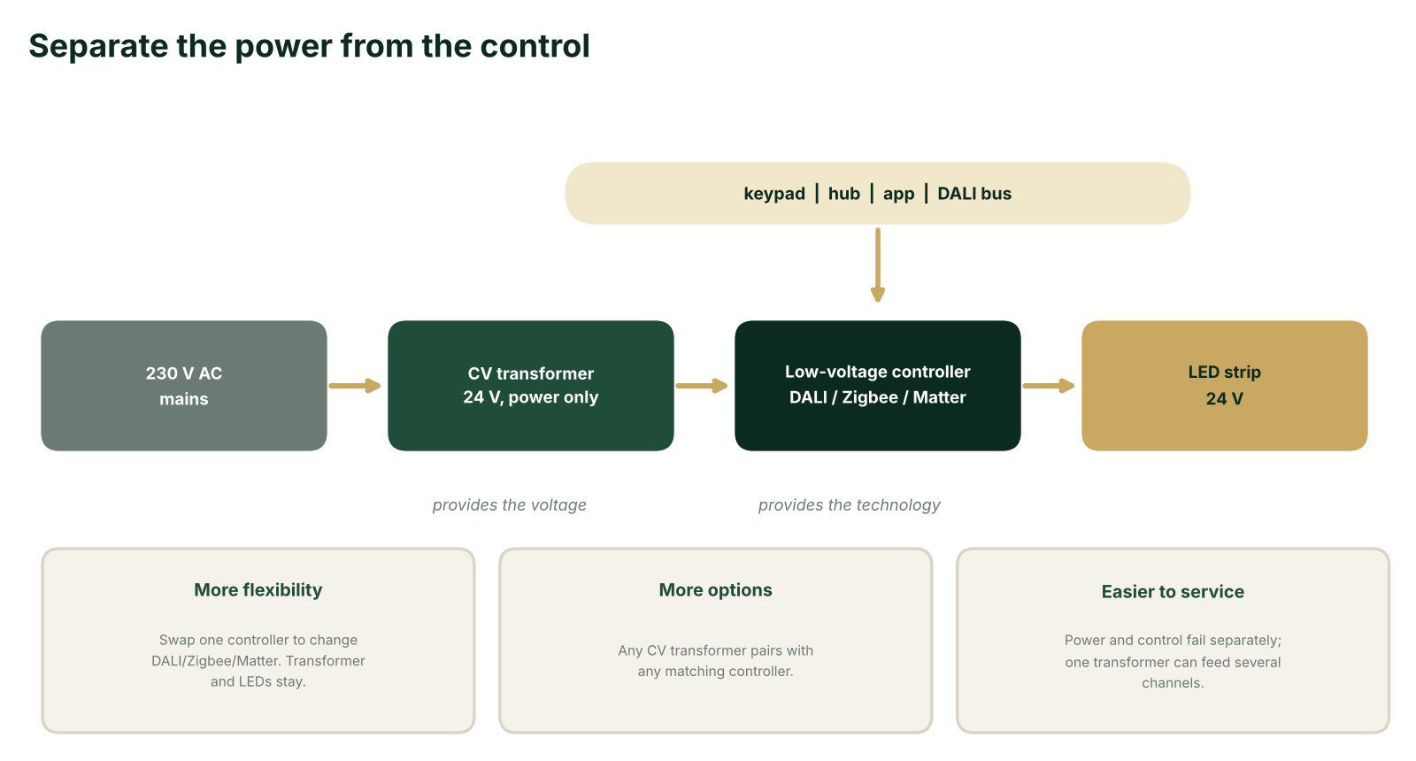
The chain is: 230 V mains, then a CV transformer (24 V, power only, "provides the voltage"), then a low-voltage controller (DALI, Zigbee or Matter, "provides the technology"), then the LED strip at 24 V. A keypad, hub, app or DALI bus talks to the controller. The controller has the same voltage on both sides and 1 to 5 channels.
More flexibility. Choose DALI, Zigbee or Matter per project, or change your mind later, by swapping one controller. The transformer and the LEDs stay.
More options. Any CV transformer can be paired with any matching controller, so you're not limited to the integrated drivers a fixture supplier offers.
Easier to service. Power and control fail independently, and one transformer can feed several controller channels or zones (watch the total load).
Scope: this pattern is for constant-voltage loads: strips and 24 V or 48 V systems. Constant-current lights (most downlight modules) need a CC driver, which normally has the control built in.
Choosing the controller: three things to match
It sits between the transformer and the LED, so it has to agree with both.
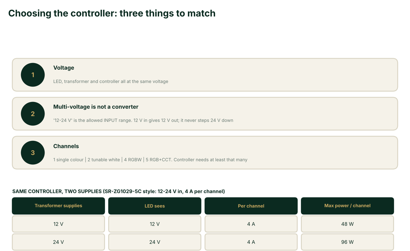
Voltage. The controller's voltage must match the LED and the transformer. All three at the same voltage: a 24 V strip, a 24 V transformer, and a controller rated for 24 V.
Multi-voltage is not a converter. A controller rated "12-24 V" accepts either supply and passes it through. 12 V from the transformer gives 12 V at the LED, and 24 V gives 24 V. It never steps 24 V down to 12 V, so the LED must still match the transformer.
Channels. The LED decides: 1 for single colour, 2 for tunable white, 4 for RGBW, 5 for RGB+CCT. The controller needs at least that many channels. Some let you pick the mode, for example a 5-channel unit with DIM, CCT, RGBW and RGB+CCT modes.
Same controller, two supplies
Take a controller like the Sunricher SR-ZG1029-5C: Zigbee, 12-24 V in, 5 channels, 4 A per channel.
Transformer supplies | LED sees | Per channel | Max power per channel |
|---|---|---|---|
12 V | 12 V | 4 A | 48 W |
24 V | 24 V | 4 A | 96 W |
The arithmetic is the teaching point: 4 A x 12 V = 48 W and 4 A x 24 V = 96 W. The "12-24 V" is an input range. These controllers are PWM, constant-voltage devices, so output voltage equals supply voltage.
Also check
Current and power per channel: keep the LED load under about 80% of the channel rating.
The transformer is sized for the sum of all channels, with headroom.
Control protocol and minimum dim level.
Mounting: ventilated, and radios out of sealed metal housings.
The "also check" list was my addition to the three core points, because per-channel current ratings and total transformer load are standard datasheet checks.
One discrepancy: the retailer page I found for the SR-ZG1029-5C (Linkshop) confirms 4 A per channel and 12/24 V, but titles it "4-in-1", while the "5C" suffix and a sibling Matter-over-Thread model's page describe five channels. Settle the channel count from the official datasheet before you quote.
Choosing a driver: seven steps, always in this order
Start from the light, never from the driver.
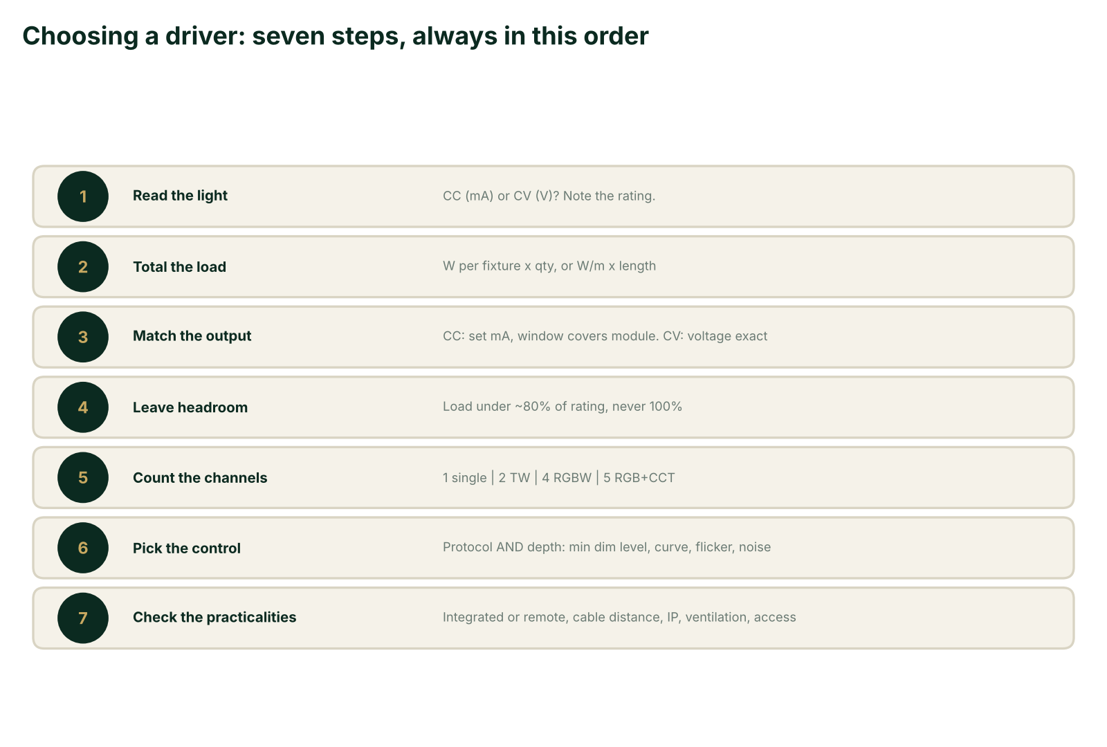
Read the light. Label or datasheet: is it CC (mA) or CV (V)? Note the rated current or voltage.
Total the load. Watts per fixture x quantity, or W/m x length for strips. One driver per load group.
Match the output. CC: set the mA and check the voltage window covers the module. CV: voltage must match exactly.
Leave headroom. Keep the load under about 80% of the driver rating (rule of thumb). Never at 100%.
Count the channels. 1 = single colour, 2 = tunable white, 4 = RGBW, 5 = RGB+CCT. The driver needs as many as the light has LED groups.
Pick the control. Protocol (phase-cut, 0-10V, DALI, Zigbee, BLE, Matter...) and depth: minimum dim level (0.1% versus 1 to 5%), curve, flicker and noise. For CV loads the control can sit in the driver or in a separate controller.
Check the practicalities. Integrated or remote? Cable distance from driver to LED (CC) or voltage drop (CV), IP rating, ventilation, access for service.
Remember: the light and the driver are independent products. A perfect driver on the wrong light is still a wrong quote.
Example 1: the downlight
Typically a CC light: the module sets the current, and the driver has to deliver exactly that.
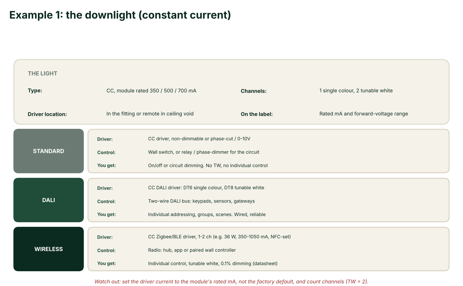
Electrical type: constant current (CC), module rated in mA, for example 350, 500 or 700 mA.
Channels: 1 for single colour, 2 for tunable white (warm and cool LED groups).
Driver location: inside the fitting, or a remote box in the ceiling void.
Read on the label: rated current (mA) and forward-voltage range (V).
Option | Driver | Controlled by | You get |
|---|---|---|---|
Standard | CC driver, non-dimmable, or phase-cut / 0-10V dimmable | Wall switch, or a relay / phase-dimmer module for the whole circuit | On/off or circuit dimming. No tunable white, no individual control |
DALI | CC DALI driver: DT6 for single colour, DT8 for tunable white | Two-wire DALI bus: keypads, sensors, gateways (Day 3) | Individual addressing, groups and scenes. Wired, reliable at scale |
Wireless | CC Zigbee / BLE driver, 1 or 2 channels, e.g. Sunricher SRP-ZG9105N-36CCT350-1050 (2 ch, 36 W, 350-1050 mA, NFC-set) | Radio: hub, app, or a paired wall controller, no control cable | Individual control, tunable white, dimming down to 0.1% (per datasheet) |
Watch out: set the driver's output current to the module's rated mA, not the factory default, and count the channels. A tunable-white downlight has two LED groups and needs a 2-channel driver.
The standard and DALI rows are generic categories, not specific part numbers. The wireless example is a real Sunricher driver, and the datasheet I found (for the sibling code SRP-9101-36-TW-C1050NFC) confirms two channels, 36 W, 350 to 1050 mA via NFC and a default of 800 mA. Another reason never to trust the default.
Example 2: the striplight, transformer plus controller
The transformer provides the voltage. The controller provides the technology.
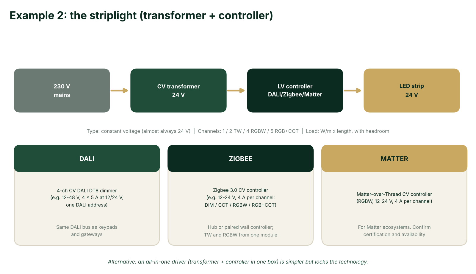
Electrical type: constant voltage (CV), almost always 24 V, sometimes 12 V.
Channels: 1 single colour, 2 tunable white, 4 RGBW, 5 RGB+CCT.
Power: a remote transformer in the DB or ceiling void.
Load: watts per metre x length. Size with headroom.
Controller | Example | You get |
|---|---|---|
DALI | 4-channel constant-voltage DALI DT8 dimmer, e.g. Sunricher: 12-48 V in/out, 4 x 5 A at 12/24 V, one DALI address | Wired and addressed: sits on the same DALI bus as your keypads and gateways (Day 3). Colour or CCT from one address |
Zigbee | Zigbee 3.0 CV controller, e.g. Sunricher SR-ZG1029-5C: 12-24 V, 5 channels, 4 A per channel; DIM / CCT / RGBW / RGB+CCT modes | Hub or paired wall controller; tunable white and RGBW from one small module |
Matter | Matter-over-Thread CV controller. Sunricher lists an RGBW model (12-24 V, 4 A per channel) | For Matter ecosystems. Confirm model, certification and availability for our market before quoting |
Alternative: an all-in-one driver (transformer and controller in one box, for example Sunricher SRP-ZG9105-24-100W-CVF, Zigbee RGBW 100 W) is simpler but locks the technology. Either way: match the voltage, count the channels, keep load under about 80%.
Striplight: all-in-one driver vs transformer plus controller
Two ways to get DALI or Zigbee control onto the same 24 V strip.
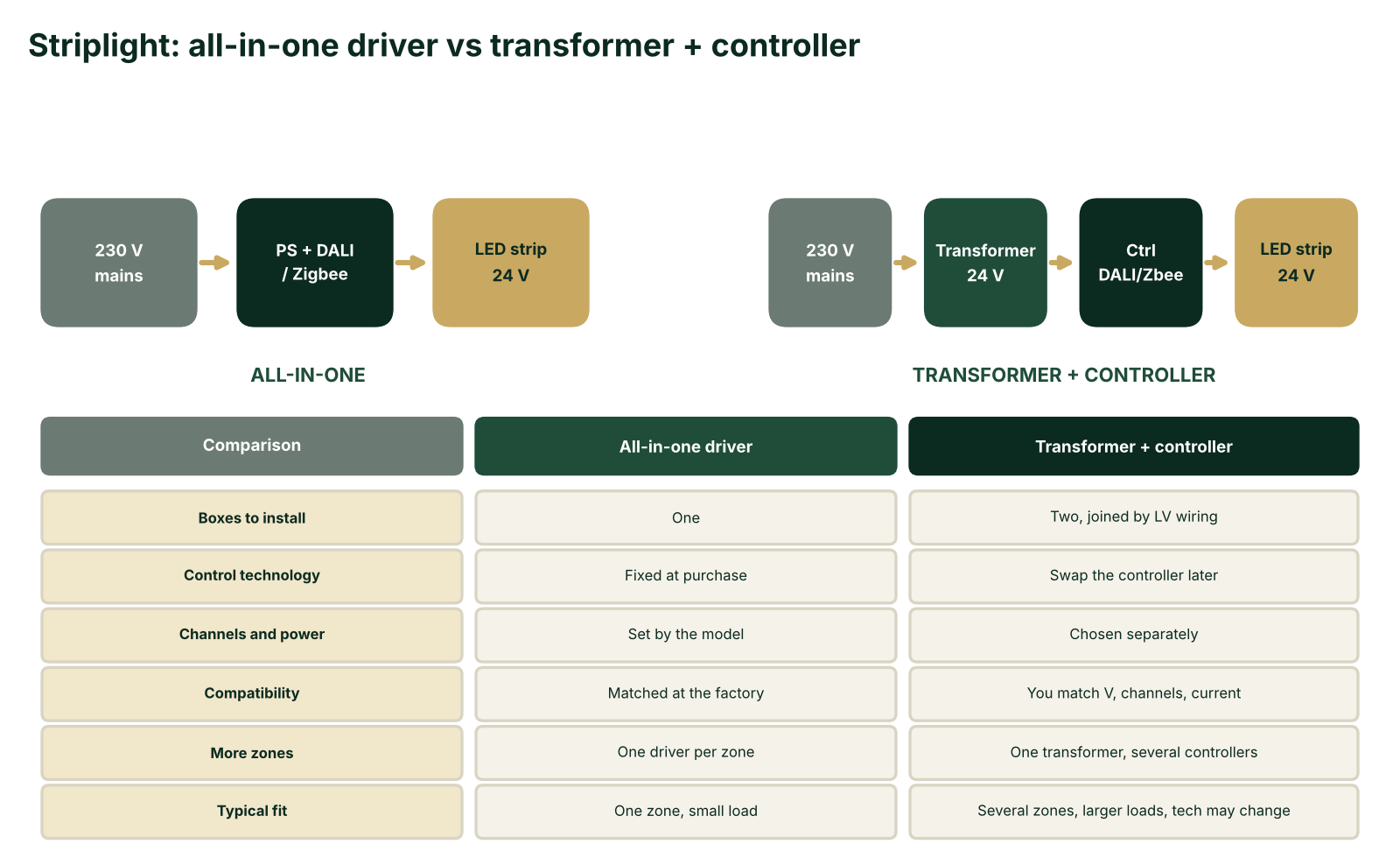
All-in-one driver: mains goes into one box (power supply plus DALI or Zigbee) and then to the 24 V strip. Examples: Sunricher SRP-ZG9105-24-100W-CVF (Zigbee RGBW, 24 V, 100 W, 4 ch) or SRPC-2309PRO-24-200CVF (DALI DT8, 200 W, 4 ch).
Transformer plus controller: mains goes to a transformer, then a controller (DALI or Zigbee), then the 24 V strip. For example any 24 V CV transformer plus a Sunricher SR-ZG1029-5C or a 4-channel CV DALI DT8 dimmer.
All-in-one driver (DALI / Zigbee) | Transformer + controller | |
|---|---|---|
Boxes to install | One | Two, joined by low-voltage wiring |
Control technology | Fixed when you buy the driver | Swap the controller later; transformer and strip stay |
Channels and power | Set by the model (e.g. 4 ch, 100 W) | Chosen separately: transformer watts, controller channels and amps |
Compatibility | Matched at the factory | You match voltage, channels and current |
More zones | One driver per zone | One transformer can feed several controllers (check total load) |
Typical fit | One zone, small load, simple install | Several zones, larger loads, technology may change |
This is a general engineering trade-off, not a price list. Cost depends on the project.
Example 3: the tracklight, anatomy and power
A 48 V magnetic track: the track, the heads, and where the transformer sits.
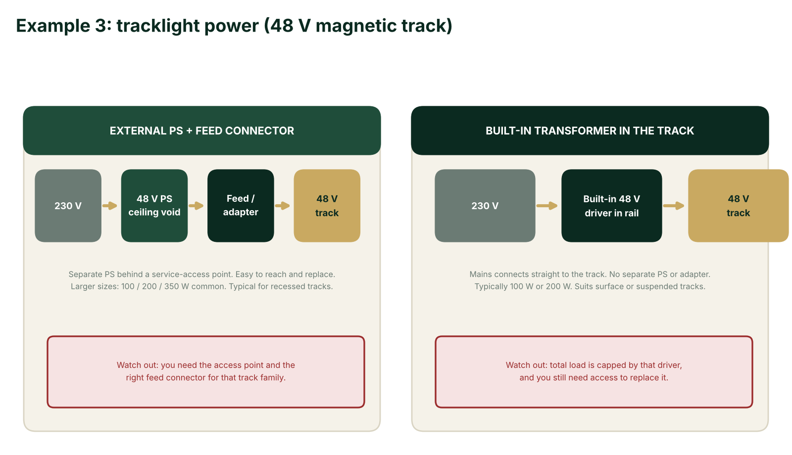
External power supply plus feed connector. A separate 48 V power supply sits in the ceiling void or behind a service-access point, and feeds the track through a power feed (end or mid feed) or input adapter. The chain is 230 V mains, the 48 V power supply, a 48 V DC cable, the power feed or adapter, then the 48 V track. It is typical for recessed tracks, and easy to reach, service and replace. Larger sizes are available (100, 200 and 350 W is common).
Watch out: you need the access point and the right feed connector for that track family.
Built-in transformer in the track. The driver is fitted inside the track rail itself. Mains connects straight to the track, with no separate power supply or input adapter. Typically 100 W or 200 W. Suited to surface-mounted or suspended tracks.
Watch out: the track's total load is capped by that driver, and you still need access to replace it.
Either way, the track carries power (and on DALI tracks a data pair). Where the control sits is the next question. Sizes and connector names vary by brand, so confirm with the supplier. My source for this slide was a set of supplier guides for 48 V magnetic track, and I did not re-verify them.
Track control, SLD A: controller at the power supply
One controller commands the whole track, so every head works as one circuit.
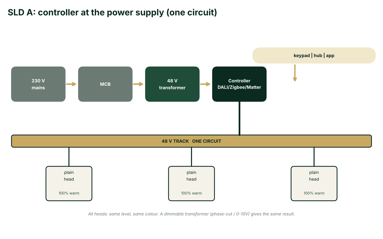
The single-line diagram runs: 230 V mains, MCB, 48 V transformer with the controller (DALI, Zigbee or Matter) built in, then the 48 V track with plain heads. A keypad, hub or app talks to the controller. A dimmable transformer (phase-cut or 0-10V) gives the same result: one circuit.
What this means:
One controller commands the whole track: one pairing or one DALI address.
Heads are plain 48 V heads with no controller inside. They are cheaper, and any matching head fits.
Every light on the track works as a single circuit: same level, same colour.
Need two zones? Use two tracks, each with its own transformer and controller.
Best for: one zone per track, such as a single wall wash or a shop counter. If the client wants to dim spots individually, this isn't the option.
Track control, SLD B: controller inside each light
A plain transformer provides the power, and every head has its own controller.
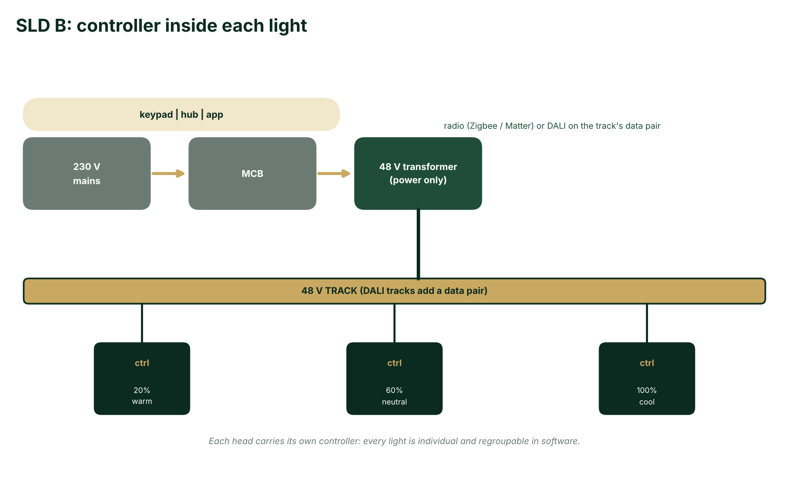
The single-line diagram runs: 230 V mains, MCB, a plain 48 V transformer (power only), then the 48 V track (DALI tracks add a data pair). Each head carries its own controller, shown here at 20% warm, 60% neutral and 100% cool. Control reaches each head by radio (Zigbee, Matter) or, on DALI tracks, over the data pair. Levels are illustrative.
What this means:
The transformer only provides the 48 V. It needs no control technology.
Each head carries its own controller (DALI, Zigbee or Matter): every light is individual and can be regrouped in software.
Heads cost more, and you commission one address or pairing per head.
Heads must be the controlled version for that track family. Confirm with the supplier.
A vs B: controller at the power supply means one circuit, simpler and cheaper heads. Controller in each head means individual lights, but more cost and commissioning per head. An example head-level product from my notes is the Sunricher SRP-2305-MT-48VCC100-700S, a DALI-2 driver for magnetic track.
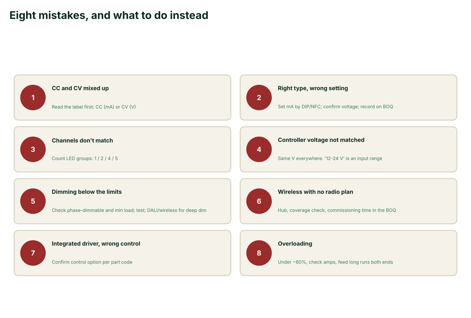
Mistakes 1 to 4: selection errors
Caught on paper they cost nothing. Caught on site they cost a visit.
Mistake and what happens | Don't | Do |
|---|---|---|
1. CC and CV mixed up. Flicker, overheating, damage | Pick a driver by wattage alone, or reuse "a spare one" | Read the light's label first: CC (mA) or CV (V). Strips and 24/48 V systems are CV; downlight modules and most track heads are CC |
2. Right type, wrong setting. LEDs over- or under-driven; 24 V on a 12 V strip can burn out at once | Trust the driver's factory-default mA, or assume the voltage | Set the mA (DIP switch / NFC) to the module's rating and confirm the voltage on the label before power-up. Record both on the BOQ and the install sheet |
3. Channels don't match. No colour mixing; part of the strip stays dark | Use a single-channel driver or controller on tunable white or RGBW | Count the LED groups or strip wires first: 1 / 2 / 4 / 5. Pick a driver or controller with at least that many channels |
4. Controller voltage not matched. Wrong voltage at the LED, damaged strip or dim output | Assume a "12-24 V" controller converts voltage, or pair a 12 V strip with a 24 V transformer | Make transformer, controller and LED the same voltage. Read "12-24 V" as the controller's allowed input range, not a selectable output |
Mistakes 5 to 8: control and sizing errors
The ones that show up after handover.
Mistake and what happens | Don't | Do |
|---|---|---|
5. Dimming below the limits. Flicker, buzzing, or no dimming at all | Phase-dim a non-dimmable driver, or load a phase-dimmer below its minimum (typically about 3 to 5 W per lamp, about 10 W per circuit) | Confirm the driver is phase-dimmable and the circuit load is above the module's minimum; test one circuit first. For deep dimming use DALI or wireless drivers specified to 0.1% |
6. Wireless with no radio plan. Dropouts, slow response, failed pairing on site | Quote wireless drivers or controllers with no hub or gateway, or bury radios in sealed metal housings | Put the hub or gateway, a coverage check and commissioning time in the BOQ. Mount controllers where the signal can get out |
7. Integrated driver, wrong control. Control technology locked: changing it means replacing the driver | Order a fitting with a built-in driver before confirming its control version | Confirm the control option (standard / DALI / wireless) per part code. Where flexibility matters, specify a fitting with a separate transformer plus controller |
8. Overloading. Shutdowns, hot hardware, dim far end of the strip | Run a transformer or controller channel at 100%, or feed a long strip from one end only | Keep each transformer and each channel under about 80% of its rating (rule of thumb), check amps per channel, and feed long runs from both ends, or use 24 V instead of 12 V |
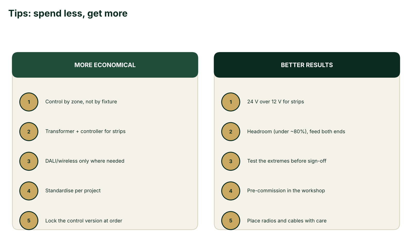
Tips: spend less, get more
Practical habits that lower the cost of the solution and raise the quality of the result.
More economical
Control by zone, not by fixture. Where individual control isn't needed, one multi-channel controller per cove run beats a driver per segment.
Use transformer plus controller for strips. One transformer can feed several controller channels (check the total load). Changing technology later means replacing one controller.
Spend on DALI or wireless only where needed. Relay modules for plain circuits and non-dimmable loads, controlled drivers for the architectural lighting.
Standardise per project. One controller family and one protocol: fewer part numbers, fewer spares, one commissioning routine.
Lock the control version at order. Swapping a built-in driver later costs a second part and a second site visit.
Better results
Prefer 24 V over 12 V for strips. Same power at half the current: less voltage drop, thinner cable, a more even strip.
Keep headroom, feed from both ends. Stay under about 80% on transformers and controller channels, and feed long runs from both ends.
Test the extremes before sign-off. Check the lowest dim level and the ends of tunable white and RGBW mixes for flicker, noise and colour shift.
Pre-commission in the workshop. Pair or address, set mA or voltage, and label channels (warm/cool, R/G/B/W). Keep one schedule: circuit, transformer, controller, address.
Place radios and cables with care. Keep controllers out of sealed metal, and keep low-voltage cable runs short and sized to the current.
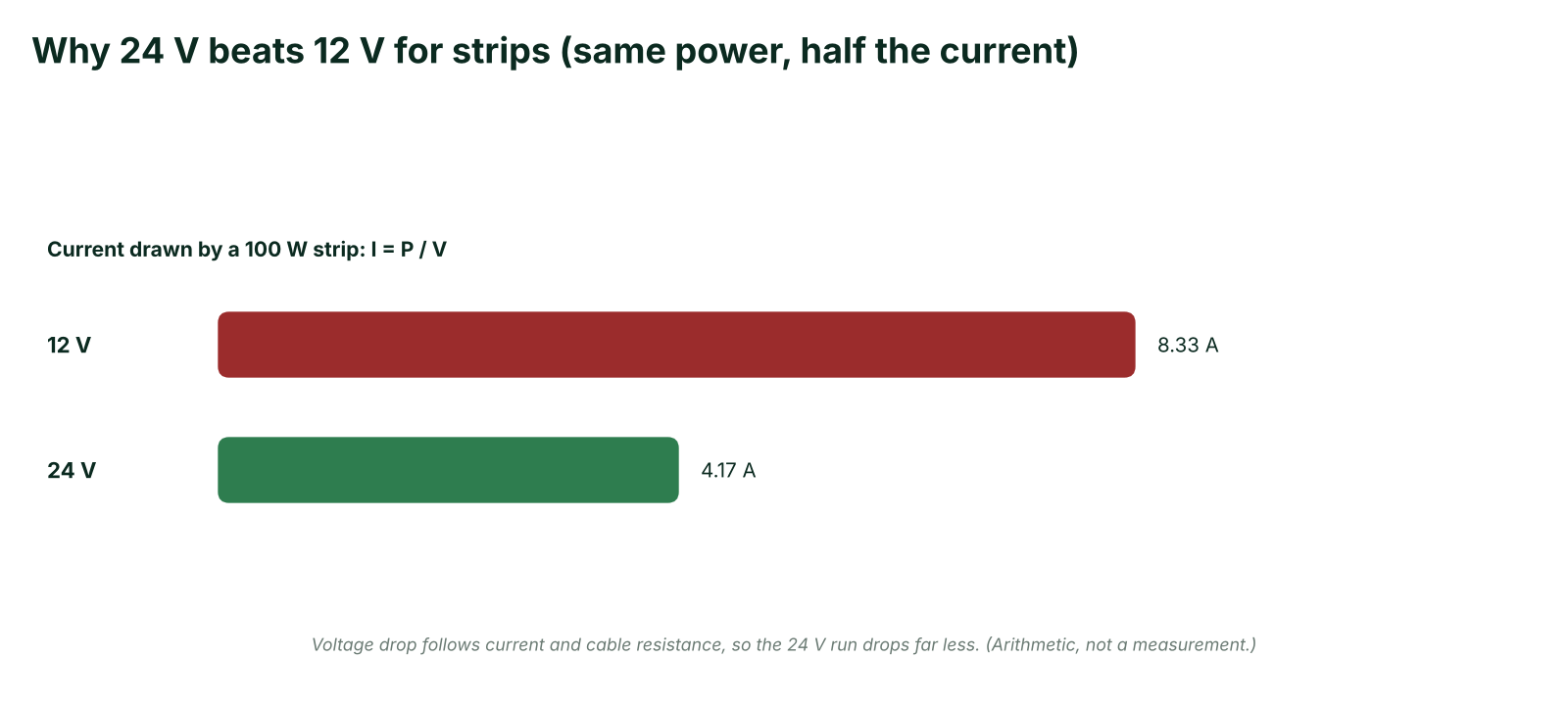
The 24 V versus 12 V point is basic physics: for the same power, current is P divided by V, so 24 V halves the current and the voltage drop along a run. Inspired LED's 12V vs 24V guide says the same: a 24 V system runs at half the current of a 12 V system for the same wattage, and voltage drop is proportional to current and wire resistance.
Scenario practice: which architecture, which driver, and what's missing?
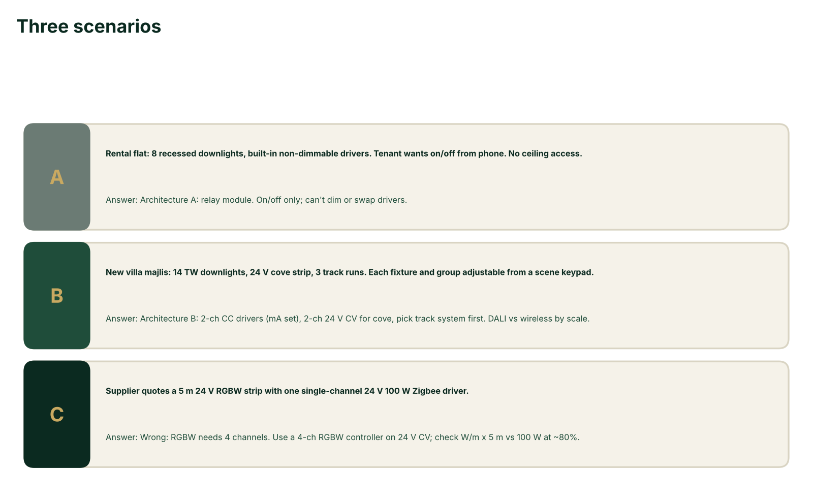
A. A rental flat: 8 recessed downlights with built-in non-dimmable drivers. The tenant wants on/off from the phone. No access above the ceiling.
Suggested answer: architecture A. A relay module gives on/off only. Dimming isn't possible with non-dimmable drivers, and nobody can swap them.
B. A new villa majlis: 14 tunable-white downlights, a 24 V cove strip and 3 track runs. The client wants each fixture and group adjustable from a scene keypad.
Suggested answer: architecture B, drivers at the light. The 14 TW downlights need 2-channel CC drivers (current set to the module). The cove needs a 2-channel 24 V CV driver, or a plain 24 V transformer plus a 2-channel controller. The track system must be chosen first. DALI versus wireless depends on scale and reliability needs (Days 1 and 3).
C. A supplier quotes a 5 m 24 V RGBW strip with "one single-channel 24 V 100 W Zigbee dimmable driver". What's wrong with the line?
Suggested answer: an RGBW strip has 4 colour channels, and a single-channel driver can't mix colours. It needs a 4-channel RGBW controller on a 24 V CV supply. Also check W/m x 5 m against the 100 W rating with about 80% headroom.
My recommendation: pick a protocol, then stay on it
The slides deliberately stayed neutral on the radio ("the radio can change; the question where the receiver lives does not"). When it comes to what I actually recommend to clients in Bahrain and Saudi Arabia, I have a clear view.
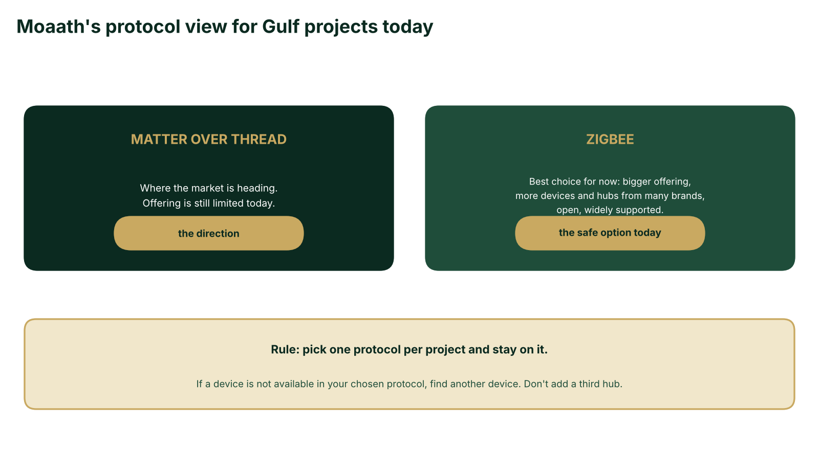
Matter over Thread is where the market is heading, but the offering is still limited today. That is the honest part. It is the technology I would point a client toward, and I would not promise them a full lighting range on it yet.
For the time being, Zigbee is my second-best option, and the one I use. The offering is bigger, with more devices and more hubs from different companies. It is the most reliable after Matter, the most supported, and open source. If a client needs a dependable system today, that is where I go.
What the research says about this view
Two points back me up, and one adds nuance.
Matter is still maturing. A January 2026 status review lists over 750 Matter products, notes that many ecosystems were still on Matter 1.2 or 1.3, and says whether cross-vendor Thread networks become stable "remains to be seen". It also reports shorter battery life on some Thread devices. I could not find lighting-specific coverage (dimmable, tunable white, colour) on those pages, so check lighting support device by device.
Zigbee's ecosystem is large. One comparison cites over 4,000 certified Zigbee products (CSA figure for 2021) against a small number for Thread. Those are older numbers, but the gap is the point.
The nuance: a March 2026 academic test of Zigbee versus Matter over Thread found Zigbee had lower overhead and faster route recovery, while Matter over Thread showed better scalability and robustness in its deepest-hop tests. The authors say the choice "is not one of absolute superiority", and the testbed was small (six nodes). So "most reliable after Matter" is my field view, not a settled lab result.
Why one protocol per project: a story from someone I know
This is the mistake 6 idea, "no plan", seen from the owner's side. A tech enthusiast I know loves new technology. Because he couldn't always find the right device in the same technology, he mixed protocols and ended up with three different hubs talking to each other. The result was daily maintenance and daily issues, and the cost of keeping it running became bigger than the benefit of the smart devices. In the end he gave up, removed everything, and had to invest again from zero.
He now buys only Matter. If he can't find a device in Matter over Thread, he simply doesn't buy it.
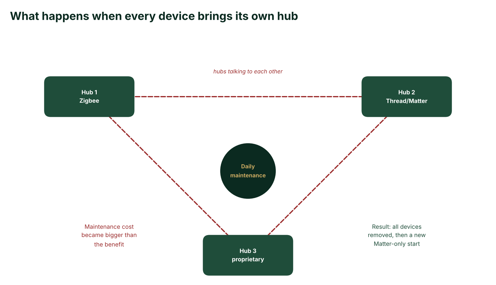
I would not copy his Matter-only rule for a client today, because the lighting offering is still thin (see above). But the lesson is the one to take: choose the protocol before choosing the devices, put the hub, coverage and commissioning in the BOQ, and when a device isn't available in your chosen protocol, change the device, not the hub count. For hybrid projects (relays on fans and pumps, wireless drivers on lights), keep them under one app or hub.
Key takeaways
Wireless comes in two architectures: a relay or dimmer at the wall (controls the circuit) or control in the light (controls the fixture).
A relay module gives on/off and, at best, main dimming. Individual control, deep dimming, tunable white and RGBW need control at the light, and the wall switch then becomes just a controller.
The light and the driver are independent products: the same fitting can be built with a standard, DALI or wireless driver.
For constant-voltage loads, separate the power from the control: a transformer provides the voltage, and a low-voltage controller provides DALI, Zigbee or Matter.
Match the controller to the LED and the transformer: same voltage (a "12-24 V" controller passes the supply through), enough channels, enough current.
On a track, control at the transformer makes it one circuit. A controller in each head gives individual lights.
Pick one protocol per project. Matter over Thread is the direction, Zigbee is the safe option today.
Figures I could not confirm
Candeo C201, C203 and C204 minimum-load figures, and the typical 3 to 5 W per lamp and 10 W per circuit. These come from my notes and vary by model.
The 0.1% dimming figure for the specific driver SRP-ZG9105N-36CCT350-1050. The Simpex datasheet for the sibling code states 0.01% to 100%.
The channel count of the SR-ZG1029-5C (one retailer says "4-in-1", the suffix says 5C).
Matter certification and local availability of Sunricher's Matter-over-Thread controller. A retailer lists it, with no certification ID.
The Sunricher 4-channel CV DALI DT8 dimmer, SRP-ZG9105-24-100W-CVF, SRPC-2309PRO-24-200CVF and SRP-2305-MT-48VCC100-700S. I did not find independent pages for these.
The 48 V magnetic track details (100, 200 and 350 W sizes, feed connectors, built-in driver sizes). Supplier guides only, not re-verified.
ENTTEC's CC/CV guide, which I could not open. For "CV driver on a CC module" I have no source beyond my training notes.
Lighting support in Matter (dimmable, tunable white, colour) was not stated on the Matter pages I read.
The 80% headroom figure is a rule of thumb, not a standard, as the slides said.
Sources
Matter standard in 2026: a status review (matter-smarthome.de)
Sunricher SR-MT1029-5C Matter over Thread controller (Power Supplies Australia)
Essentia Lighting & Control, Day 4 training deck (Wireless Lighting Control, draft for review)
Comments
Be the first to comment.
Questions about this article
What are the two ways to make a light wireless?
Control the circuit with a relay or dimmer at the wall, or control the light with a wireless driver in each fixture. The key question is where the receiver lives.
What can a wall relay or dimmer module do?
It gives on/off per circuit from an app, voice, schedule or scene. It also dims the circuit, but only if every driver on it is phase-dimmable.
Can a wall module give tunable white or colour?
No. The module only sees mains voltage, and everything on the circuit moves together with the same level.
What does a wireless driver at the fixture add?
Each fixture or group is controlled separately and can be regrouped in software. It also allows deep dimming, tunable white with 2 channels, and RGBW with 4 to 5 channels.
Which approach suits a retrofit with no ceiling access?
The wall relay or dimmer is strong here because the existing fixtures stay. The wireless driver route needs drivers swapped or fixtures supplied wireless.
When is a wireless driver the better choice?
It fits new builds or open ceilings, and projects needing deep dimming, tunable white or colour. It also suits individual or flexible grouping, provided a radio plan exists.
Can both approaches be used in one project?
Yes, hybrid is normal. Use wireless drivers on the architectural lighting and relay modules on fans, pumps and non-dimmable loads, all under one app or hub.
What is the difference between CC and CV drivers?
A CC driver gives a fixed current in mA with floating voltage, and suits downlight modules, COB and track heads. A CV driver gives a fixed voltage, typically 12 V or 24 V, and suits LED strips.
What happens if the driver doesn't match the light?
A CC driver on a CV strip causes flicker, overheating and damage. A CV driver on a CC module gives uncontrolled current, and 24 V on a 12 V strip can burn it out at once.
Why use a transformer plus a low-voltage controller?
The transformer provides only the voltage and the controller provides the technology. You can switch between DALI, Zigbee or Matter by swapping one controller, while the transformer and LEDs stay.
What should I match when choosing a controller?
The voltage must match the LED and the transformer. The channels must match the LED: 1 for single colour, 2 for tunable white, 4 for RGBW and 5 for RGB+CCT.
Does a 12-24 V controller convert 24 V down to 12 V?
No, "12-24 V" is an input range and the controller passes the supply voltage through. For example, the Sunricher SR-ZG1029-5C at 4 A per channel gives 48 W at 12 V and 96 W at 24 V.
Planning a project?
Talk to our engineers about lighting, control and automation for your space.